
In the last blog post, we discussed the benefits and use cases of ultra-wideband (UWB), and how secure and accurate UWB is compared to other wireless technologies. Today, we will clarify some of the commonly used technical terms that are associated with UWB. Don’t let all the acronyms deter you from diving deeper into the world of UWB!
UWB derives its name from its wide bandwidth, 500 MHz or wider. This ultra-wide bandwidth in the frequency domain, translates into extremely short, nano-second pulses in the time domain, giving UWB its unique capability to measure distances with an accuracy of tens of centimeters. We will first define the two commonly-used terms associated with distance measurements: Time of Flight (ToF) and Two-Way Ranging (TWR).
Time of Flight (ToF)
ToF refers to the duration it takes for a signal to travel from one point to another. Just as the name implies, ToF is the time it takes for a signal to “fly” between two devices. Using the formula, distance = velocity x time, which we learned in elementary school, we can calculate the distance as the speed of light, at which the wireless signals travel, multiplied by the ToF.
Two-Way Ranging (TWR)
Two-Way Ranging (TWR) refers to the distance measurement method based on ToF, as a result of bidirectional communication between two devices. There are two types of TWR: Single-Sided (SS) and Double-Sided (DS). In Single-Sided, or One-Sided TWR, one UWB device, an initiator, sends a signal, and another UWB device, a responder, detects it and replies back with a time-stamped response. Knowing the time it took for the UWB signal to travel from the initiator to the responder and back to the initiator, and dividing it by two (because it was a roundtrip), you can estimate the ToF from SS-TWR. The other method, Double-Sided TWR, is similar to SS-TWR, except that the initiator sends back another response to the responder. This extra response offers added accuracy to the ToF estimation.
Although ToF provides accurate distance measurements, it alone does not give you the exact location of UWB devices. For example, if your smartphone reports that your UWB tag is five meters away based on the ToF alone, you have no idea if it is located 5 meters to your right or five meters to your left.
To address this limitation, you would need another dimension in the geometry to determine the exact spatial location. One of the techniques used in UWB is called Angle-of-Arrival, or AoA. Let’s explore how AoA works in UWB systems.
Phase Difference of Arrival (PDoA)
To enable the AoA mechanism, a stationary UWB device (an “anchor”) must be equipped with multiple antennas to locate a sought UWB device (a “tag”). Let’s consider a scenario where the anchor has two antennas. When the tag transmits signals, the anchor receives two signals, one at each antenna. If the tag is located at an offset, or at an angle relative to the anchor, there will be a phase difference between the received signals at the two antennas, as the signals will arrive at one antenna sooner than at the other antenna. This phase difference is called Phase Difference of Arrival (PDoA).
Angle of Arrival (AoA)
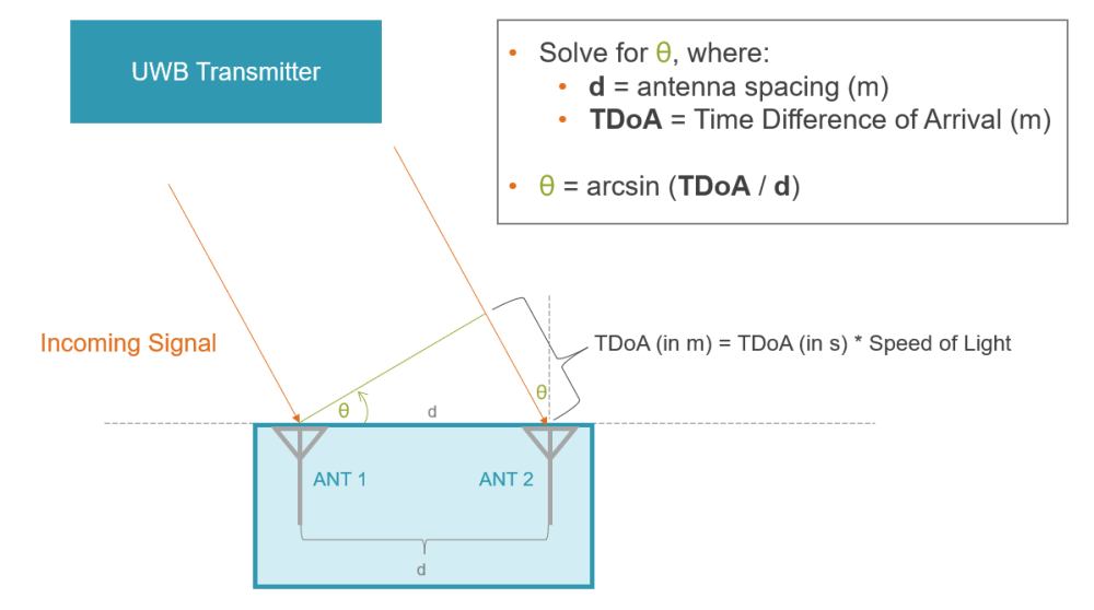
Once you have the PDoA, you can convert this difference in phase into a difference in time by dividing it by the carrier frequency, then into a difference in distance. If you remember in the earlier step, wireless signals travel at the speed of light, so the conversion is again, distance = time x the speed of light. We can now use the geometry we learned in 10th grade, the distance between the anchor’s two antennas, and the TDoA in meters, to calculate the angle at which the tag’s signal arrived at the receiver. The derived angle is called Angle of Arrival (AoA).
Watch the FiRa Presents video to learn more about AoA.
By combining the distance between the tag and the anchor, obtained from ToF measurements, and the angle formed between the tag and the anchor, or AoA, it is simple to determine the precise, relative location of the UWB devices
Putting it All Together with UWB
Given its exceptional accuracy in determining the precise positioning of devices, UWB is used in various mission-critical applications such as location services, secure access, and asset tracking. Understanding the methodologies underlying UWB, such as ToF and AoA, it becomes evident that validating the accuracy of each UWB device, such as its carrier frequency and pulse shape, ensures the overall effectiveness of UWB-based systems. Part of FiRa Consortium’s certification process involves guaranteeing the RF performance of UWB devices, assuring that each certified device is capable of delivering the required accuracy, which is vital and unique to how UWB functions. For more information about FiRa’s certification program, please see the Certification Page.
By Yuka Muto, Product Marketing Manager at LitePoint