Introduction
Ultra-wideband (UWB) is a short-range, wireless technology that makes use of wideband radio waves. Compared to Wi-Fi or Bluetooth®, UWB operates in higher frequency bands and uses a wider bandwidth (500 megahertz or more). These special characteristics of UWB allow it to measure distance and to determine position much more accurately than other technologies, providing the basis for building more secure applications.
After decades of discussion and development, UWB technology is now demonstrating its potential and quickly becoming a vital mainstream wireless technology like Wi-Fi and Bluetooth®.
As such, FiRaTM Consortium recommends preserving the 7.7–9.3 GHz band for UWB, not to study and create identifications for International Mobile Telecommunications (IMT) in this band.

Social and Economic Impact
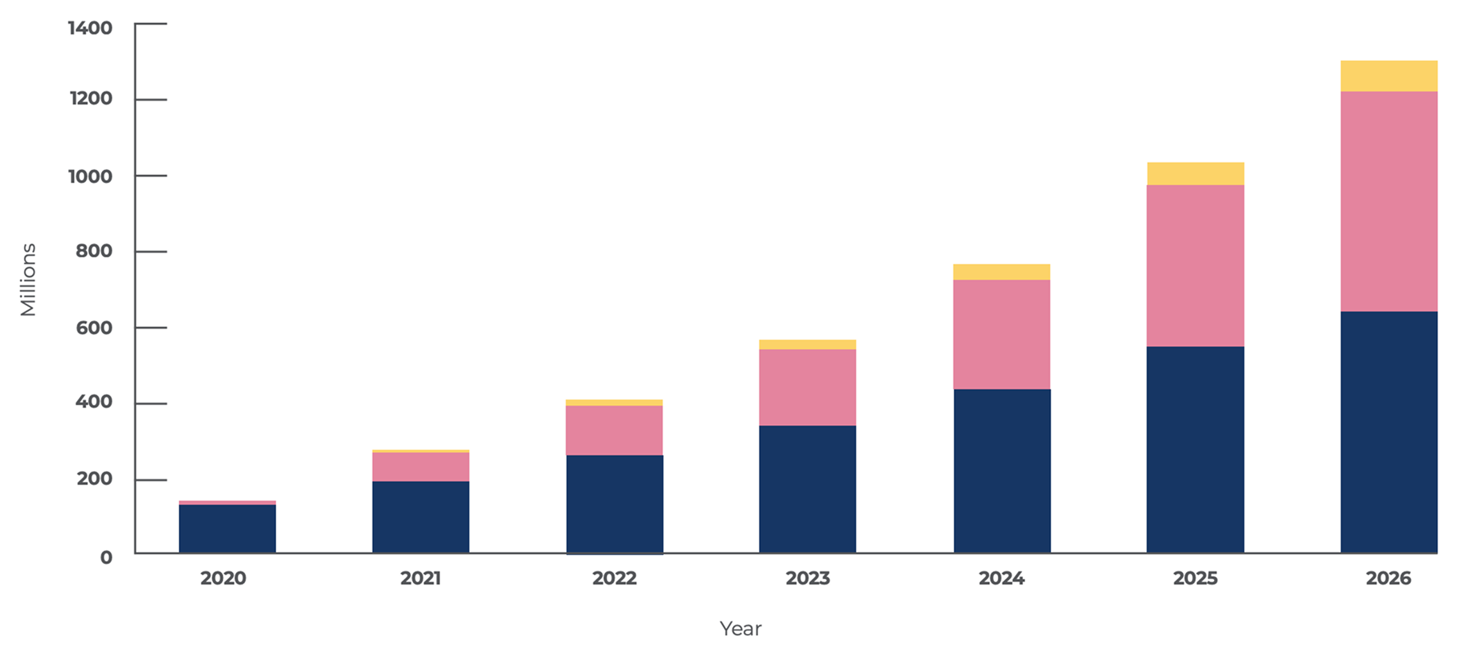
One data point that supports the expected growth of UWB is from ABI Research. Figure 1 shows that UWB enabled devices shipped globally are poised to grow to over 1 billion devices by 2025. In fact, the UWB market is projected to grow by double digit percentages for the foreseeable future.
The other segments driving growth of UWB are Internet of Things (IoT) and Real-Time Location Systems (RTLS). There is a rising demand for UWB technology in RTLS applications. In a report published in April 2023, MarketsandMarkets estimated that the global indoor location market will grow from about $8.8 billion this year to $24 billion by 2024, a CAGR of nearly 23%.2
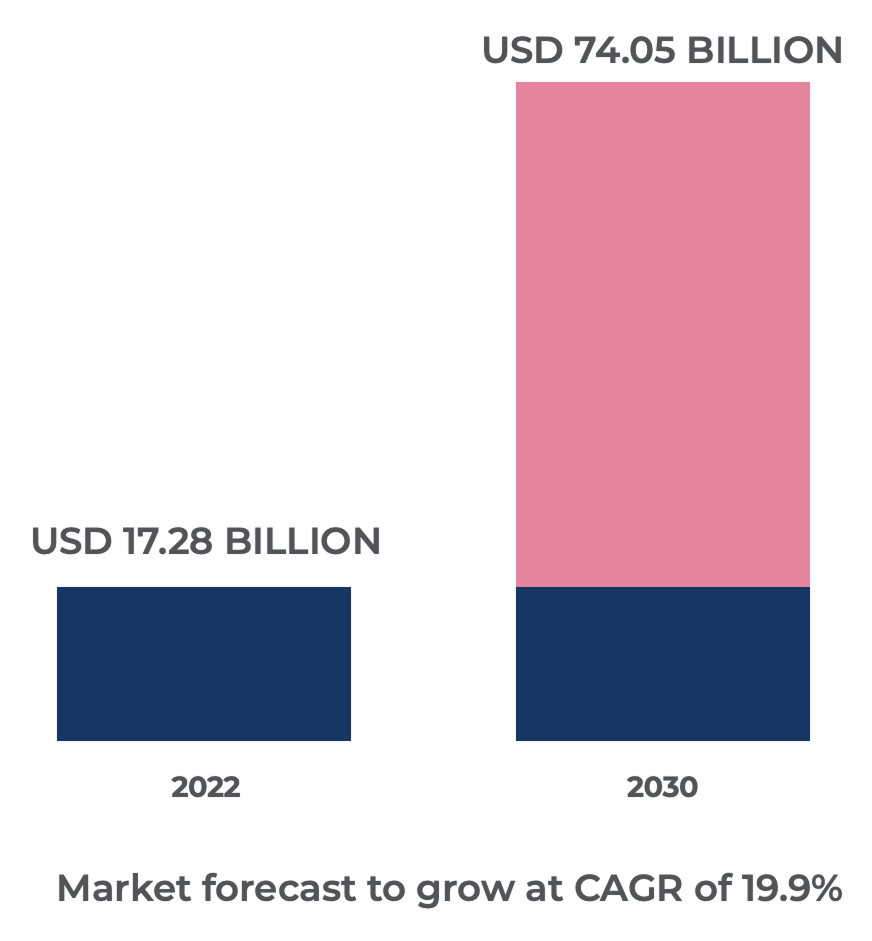
Furthermore, as shown in Figure 2 to the right, a report from Research and Markets indicated that the global indoor location-based services market size was estimated at USD 17.28 billion in 2022, and is projected to grow at a CAGR of 19.9% to reach USD 74.05 billion in 2030.3
UWB Has Tremendous Potential
In the early 2000s, UWB was foreseen to be used for local high-speed data communication, which never materialized in the market. More recently, UWB is having a renaissance and is now being used in applications in professional settings such as industrial environments.
Since 2019, the addition of the secure fine ranging feature (standardized in IEEE 802.15.4z) has led to adoption in mass market consumer products including devices such smartphones and smart watches.
Today, there are many real-world examples of UWB being used to address consumer needs for convenience, safety, health, or enjoyment.
Examples include:
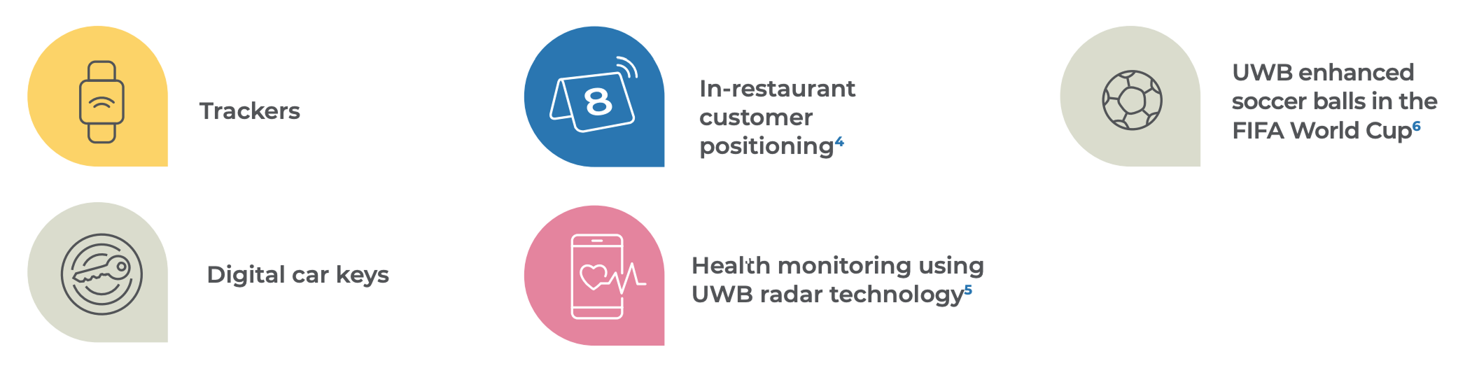
There is also interest and on-going work in the area of child presence detection systems7 using UWB in locked cars. This is clearly an important use case in the “safety” category.

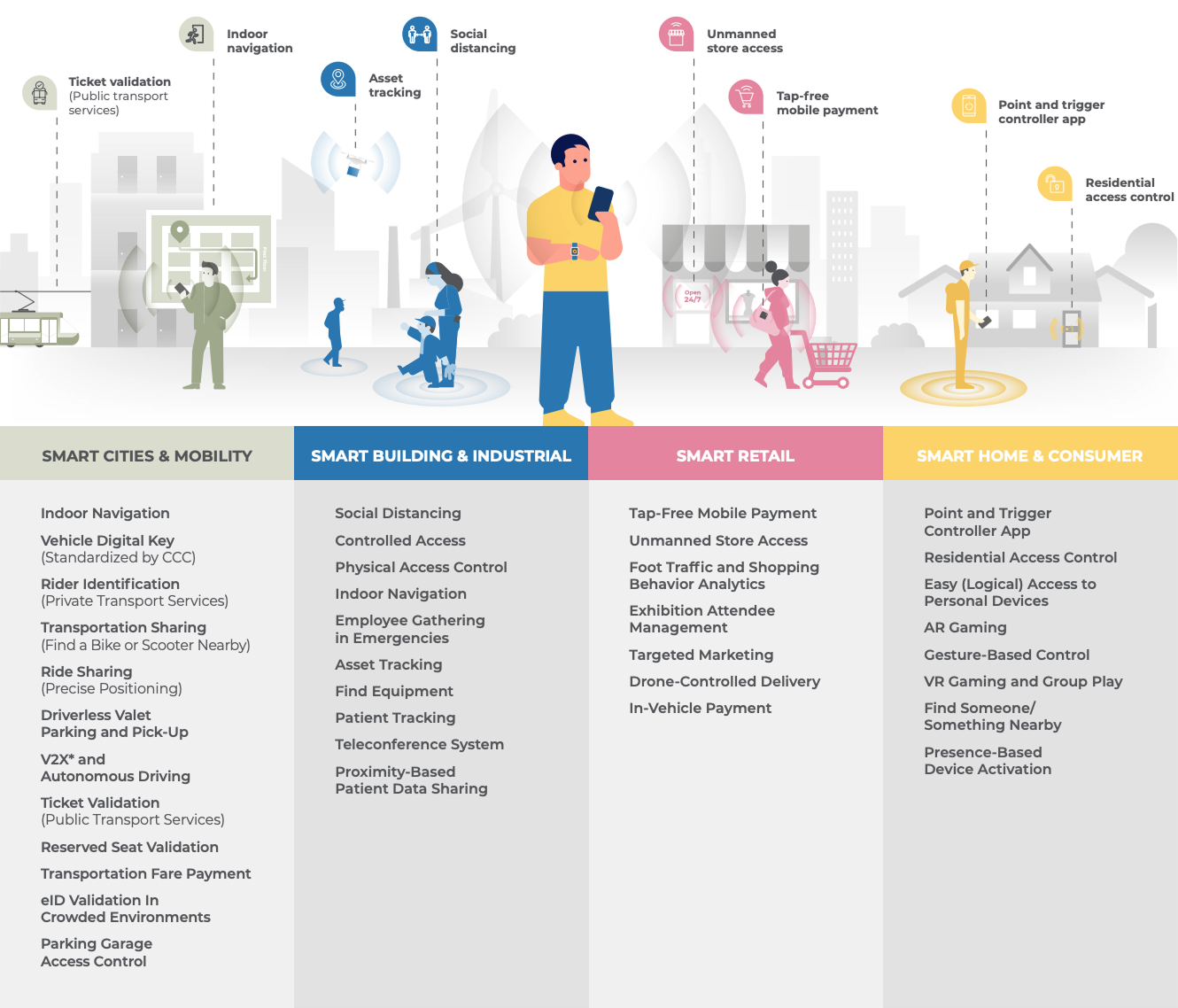
FiRa has identified a wide variety of use cases for UWB across four (4) primary market segments:

Specific use cases within each of these primary market segments are shown in Figure 3. Initial areas of focus for FiRa include IoT, secure access, tracking, and navigation. Select use cases detailed below include Access Control, RTLS, Personal and Consumer Device Tracking, and Smart Homes, driving personalized, position aware automation, and secure applications for the future automated society.
Preserve Spectrum for UWB
UWB and IMT in the same band do not coexist well
UWB applications can coexist extremely well with incumbent spectrum applications in the 6-10 GHz band. As incumbent transmitter deployment is highly localized and UWB transmissions have a very low power and duty cycle, there is no interference with incumbent receivers. However, UWB performance will be unreliable in an IMT band because ubiquitous higher-power IMT transmitters will cause interference to UWB receivers in many situations. Studies conducted by FiRa members show that interference from IMT causes more than 3 dB sensitivity reduction in UWB receivers for 75% and 95% of the events for outdoor macro urban and indoor small cells, respectively. Those events of 75% and 95% caused significant link coverage reduction (more than 30% loss) and significantly longer delay time (e.g., 0.1 s to 100 s for outdoor and beyond any practical usability [320,000 s] for indoor). Further details are provided in the Annex of this document.
IMT spectrum identification should recognize UWB market development
At WRC-23, the IMT community will strive to establish the 6 GHz band for IMT identification in specific regions. This overlaps with UWB channels 5 and 6 (6.2-7.3 GHz), which, as a consequence, can no longer be regarded as primary UWB channels.
Furthermore, at WRC-23, the IMT community plans to introduce a new agenda item proposal for WRC-27 to identify more bands for IMT in the 7-24 GHz band, particularly in the lower portion. Such proposals are likely to overlap with UWB channels currently being put in use in the 7-10 GHz band.
FiRa Consortium recommends preserving the 7.7–9.3 GHz band for UWB, and not to study and identify this band for IMT
UWB requires an unencumbered safe space in the spectrum to fully develop the growing palette of highly valuable UWB applications. The 7.7–9.3 GHz band covers UWB channels 9, 10, and 12. These channels, specifically channel 9, are deemed essential for the development of UWB’s potential. UWB combines well with the incumbent spectrum applications in the band. Therefore, FiRa recommends preserving the 7.7–9.3 GHz band for UWB, and not to create identifications for IMT in this band.

Annex
Interference Impact of IMT on UWB
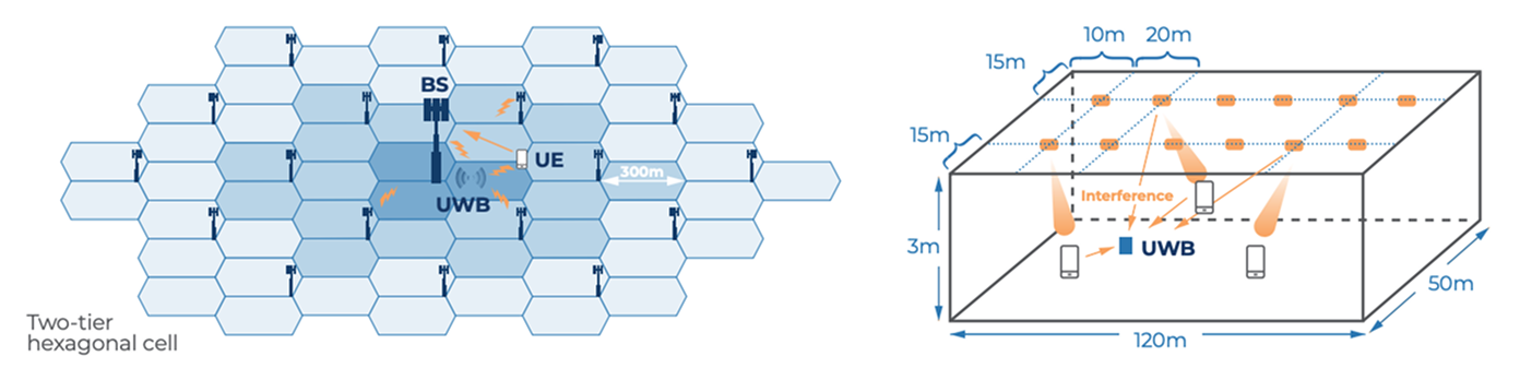
UWB applications have already been distributed globally and are used ubiquitously (i.e., both outdoor and indoor). In this regard, when IMT is introduced into bands used by UWB, it is necessary to evaluate how much interference from IMT is caused to existing and future UWB applications. Therefore, two Monte Carlo simulations were carried out. Both evaluate the effect of IMT systems on the performance of co-located UWB deployments. One considers outdoor macro urban IMT cells, while the other looks at indoor small cell IMT deployments.
Simulation Modelling
UWB deployment characteristics
The configuration of UWB is generally set up as a victim receiving interference from IMT. On the other hand, the interference criteria of -78 dBm/500 MHz for UWB is referred to in the ECC Report 302.
IMT deployment characteristics
The outdoor deployment configuration of IMT is based on sharing studies of WRC-23 A.I. 1.2 in ITU-R8.
The indoor deployment configuration of IMT is based on 3GPP TR 38.9019. In addition, the technical and operational characteristics of IMT are based on sharing studies of WRC-23 A.I. 1.2 in ITU-R.
Monte Carlo Simulation Results
The results are summarized in Figure A-2. It shows significant interference from IMT to UWB in the two deployment environments. UWB gets unacceptable interference in 75% of the events in an outdoor macro urban cell. In the indoor office small cell, the interference increases to 95% of the events.1

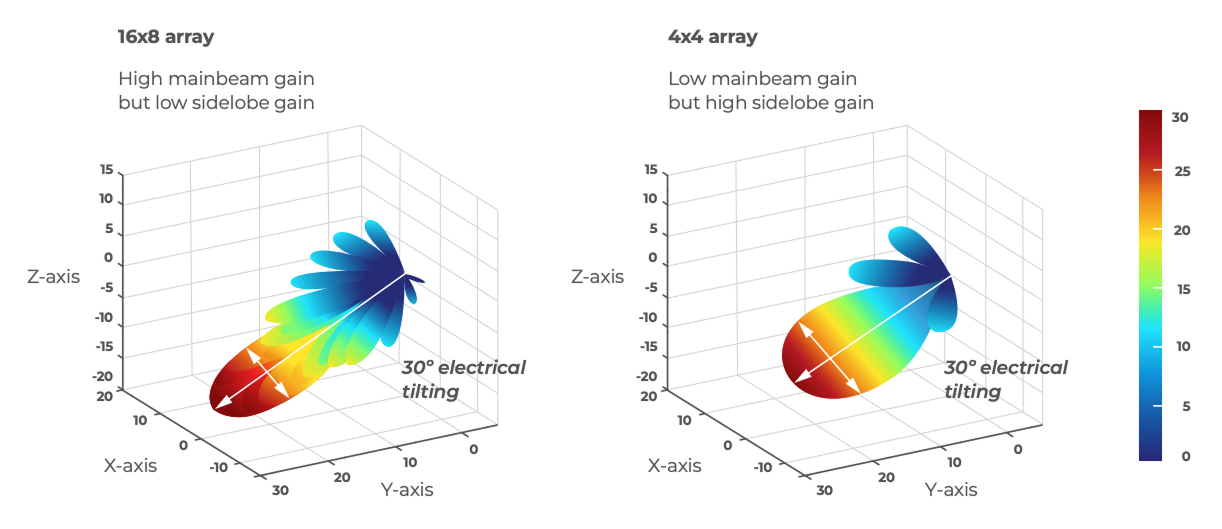
For outdoor IMT deployments, the base station (BS) employs beamforming towards the target user equipment. The higher power of the BS causes significant interference to many UWB devices far away from BS in the main beam direction. On the other hand, for indoor IMT deployments, the BS has lower transmitted power but covers a wider area and is positioned closer to the UWB device than in outdoor scenarios. The indoor base stations, therefore, cause more significant interference to UWB devices
Consequently, it can be concluded that UWB cannot coexist with either of the considered IMT deployments. Both urban macro cell IMT and indoor small cell IMT cause unacceptable levels of interference.
Practical Performance Impact of IMT on UWB
Performance impact on UWB coverage
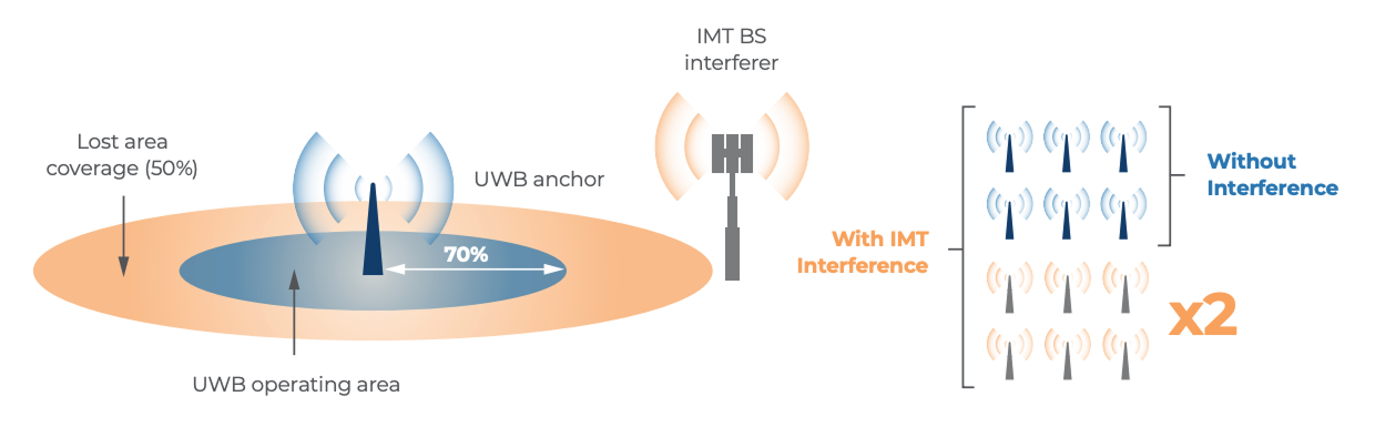
A 3 dB sensitivity reduction implies that:
- Range of the transmission is reduced to 70% of its initial coverage; and
- Area of coverage is halved (i.e., proportional to r2 ) meaning about twice as many anchors (UWB beacons) are needed to cover a given area.
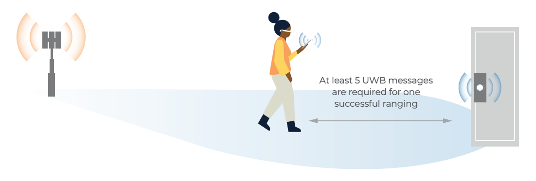
Response time (delay) degradation in UWB door lock case
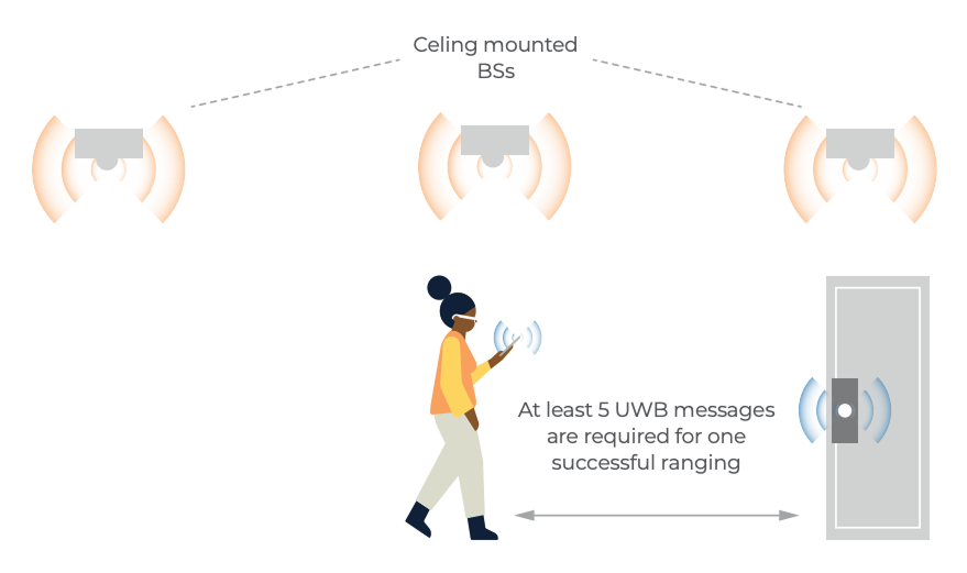
For 75% of the events in outdoor macro urban cells, the interference impact will be worse than 3 dB sensitivity reduction. If packet reception probability is reduced by 75% (i.e., from 1 to ¼), then the probability that the UWB device will correctly receive all five messages required to open the door is reduced to 1/1024 (i.e. (¼)5 ). Taking into account that the minimum interval between each trial is about 0.1 s, that means the expected delay is increased from 0.1 s to 102.4 s (i.e., 1024 x 0.1 s).
The situation is even worse for indoor deployments. There, for 95% of the events, the interference impact will be worse than 3 dB sensitivity reduction.
If the packet reception probability is reduced by 95% (i.e., from 1 to 1/20), then the probability that the UWB device will correctly receive all five messages required to open the door is reduced to 1/3,200,000 (i.e., (1/20)5 ). Taking into account that the minimum interval between each trial is about 0.1 s, that means the expected delay is increased from 0.1 s to 320,000 s (i.e., 3,200,000 x 0.1 s).
Conclusions
Monte Carlo analysis using assumptions agreed in ITU-R WP 5D presented evidence of a high risk of interference in both outdoor macro urban environments and indoor small cell environments. The Monte Carlo analysis demonstrates that the interference from IMT is higher than -78 dBm in 500 MHz for 75% and 95% of the events11 for outdoor macro urban and indoor small cell, respectively (assuming a single channel IMT operation of 100 MHz). Those events of 75% and 95% caused significant link coverage reduction (e.g., more than 30% coverage distance loss) and a significantly longer delay time (e.g., 0.1 s to 100 s for outdoor and beyond any practical usability [320,000 s] for indoor).